
amber rose
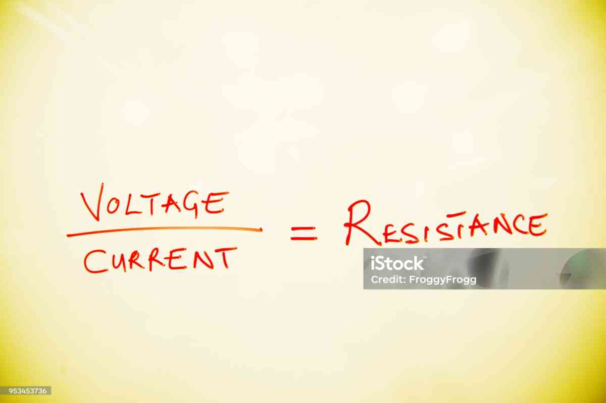
Introduction
Electrical circuits often contain multiple resistors that work together to control current and voltage. One of the simplest and most important configurations is a series resistor circuit.
When resistors are connected in series, their individual resistance values are added together to determine the total or equivalent resistance.
A Series Resistance Calculator is a free online tool that makes this calculation fast and convenient. Instead of manually adding several resistor values, you can enter them into the calculator and immediately determine the combined resistance.
The fundamental formula is:
Rtotal = R1 + R2 + R3 + … + Rn
For example, consider four resistors:
- R1 = 100 Ω
- R2 = 220 Ω
- R3 = 330 Ω
- R4 = 470 Ω
The total resistance is:
Rtotal = 100 + 220 + 330 + 470
Rtotal = 1,120 Ω
Therefore:
Rtotal = 1.12 kΩ
This simple calculation is useful in electronics, electrical engineering, robotics, automotive systems, industrial controls, laboratory experiments, educational projects, and circuit troubleshooting.
However, understanding series resistance involves much more than adding numbers. Once total resistance has been calculated, it can be used to determine current, voltage drops, power dissipation, voltage-divider outputs, and resistor requirements.
This guide explains everything you need to know about series resistance and how a free Series Resistance Calculator can help with circuit analysis.
What Is a Series Resistance Calculator?
A Series Resistance Calculator is an online electrical tool designed to calculate the combined resistance of multiple resistors connected in series.
The calculator uses the standard equation:
Rtotal = R1 + R2 + R3 + … + Rn
Users can enter two or more resistor values and obtain the equivalent resistance.
For example:
R1 = 250 Ω
R2 = 500 Ω
R3 = 750 Ω
Then:
Rtotal = 250 + 500 + 750
Rtotal = 1,500 Ω
or:
1.5 kΩ
The calculator is especially useful when working with many resistor values or when values are expressed using different units.
What Does “Connected in Series” Mean?
Two or more components are connected in series when they form a single continuous current path.
A simple resistor chain can be represented as:
Source → R1 → R2 → R3 → Source
The current must pass through R1, then R2, then R3.
There is no alternate path between these components.
As a result, the same current flows through every resistor.
If:
I = 25 mA
then:
I1 = I2 = I3 = 25 mA
This property distinguishes series circuits from parallel circuits.
Basic Series Resistance Formula
The standard formula is:
Rtotal = R1 + R2 + R3 + … + Rn
Where:
- Rtotal = total resistance
- R1 = resistance of resistor 1
- R2 = resistance of resistor 2
- R3 = resistance of resistor 3
- Rn = resistance of the final resistor
There is no special reciprocal calculation for a simple series resistor network.
Simply add the resistance values.
Why Do Series Resistances Add?
The mathematical reason comes from Ohm’s Law.
Ohm’s Law states:
V = IR
Consider two resistors connected in series.
Because the same current flows through both:
V1 = IR1
and:
V2 = IR2
The total voltage is:
Vtotal = V1 + V2
Substituting:
Vtotal = IR1 + IR2
Factor out current:
Vtotal = I(R1 + R2)
Since:
Vtotal = IRtotal
then:
Rtotal = R1 + R2
The same reasoning applies to any number of series resistors.
How to Calculate Series Resistance Manually
The calculation requires only three basic steps.
Step 1: List all resistors
For example:
- 100 Ω
- 150 Ω
- 250 Ω
- 500 Ω
Step 2: Add the values
100 + 150 + 250 + 500
Step 3: Determine the total
Rtotal = 1,000 Ω
Therefore:
Rtotal = 1 kΩ
This is exactly what the Series Resistance Calculator automates.
Example with Six Resistors
Suppose a circuit has:
- R1 = 10 Ω
- R2 = 20 Ω
- R3 = 30 Ω
- R4 = 40 Ω
- R5 = 50 Ω
- R6 = 60 Ω
Total resistance:
Rtotal = 10 + 20 + 30 + 40 + 50 + 60
Rtotal = 210 Ω
The equivalent resistance is:
210 Ω
With a large number of resistors, an online calculator can make this type of calculation more convenient.
Why Use a Free Series Resistance Calculator?
A calculator can provide several advantages.
Faster calculations
You can enter multiple values without manually adding them.
Fewer arithmetic mistakes
This is especially useful when many resistors are involved.
Convenient unit handling
Some calculators can handle Ω, kΩ, and MΩ.
Easy circuit verification
You can compare the calculator result with your design calculations.
Helpful for students
It provides an easy way to check homework and laboratory calculations.
Useful for engineers
Designers can quickly evaluate different resistor combinations.
Convenient for hobbyists
DIY electronics projects often require rapid resistor-value calculations.
Series Resistance and Ohm’s Law
Total series resistance is closely related to Ohm’s Law.
The basic equation is:
V = IR
Rearranged for current:
I = V/R
Once total resistance is known, you can calculate current through the entire series circuit.
Example
Supply voltage:
12 V
Total resistance:
1,200 Ω
Current:
I = 12/1,200
I = 0.01 A
Therefore:
I = 10 mA
This 10 mA current flows through every resistor in the simple series network.
How Resistance Affects Current
For a fixed voltage source, resistance and current have an inverse relationship.
The equation is:
I = V/R
If resistance increases, current decreases.
If resistance decreases, current increases.
Example
At 12 V:
With 600 Ω:
I = 12/600 = 20 mA
With 1,200 Ω:
I = 12/1,200 = 10 mA
With 2,400 Ω:
I = 12/2,400 = 5 mA
This demonstrates why series resistance is commonly used for current limiting.
Current in a Series Circuit
One of the defining rules of series circuits is:
The current is the same through every component in the series path.
If:
Itotal = 15 mA
then:
I1 = I2 = I3 = 15 mA
This makes series circuits particularly easy to analyze.
The resistance values determine how much voltage each resistor consumes, but the current remains the same.
Voltage in a Series Circuit
Voltage behaves differently from current.
The source voltage is divided among the resistors.
The total voltage is:
Vtotal = V1 + V2 + V3 + … + Vn
For each resistor:
Vn = I × Rn
Therefore, larger resistors have larger voltage drops when the same current flows through them.
Example of Voltage Distribution
Consider a 10 V source connected to:
- R1 = 100 Ω
- R2 = 200 Ω
- R3 = 700 Ω
Total:
Rtotal = 1,000 Ω
Current:
I = 10/1,000
I = 0.01 A
Voltage across R1:
V1 = 0.01 × 100 = 1 V
Voltage across R2:
V2 = 0.01 × 200 = 2 V
Voltage across R3:
V3 = 0.01 × 700 = 7 V
Total:
1 + 2 + 7 = 10 V
This confirms the voltage-divider behavior.
Series Resistance as a Voltage Divider
A series resistor network can be used as a voltage divider.
For two resistors:
Vout = Vin × R2/(R1 + R2)
Suppose:
Vin = 12 V
R1 = 3 kΩ
R2 = 1 kΩ
Total:
4 kΩ
Output across R2:
Vout = 12 × 1/4
Vout = 3 V
This simple arrangement is commonly used to generate a lower voltage from a higher voltage.
Three-Resistor Voltage Divider
The same concept can be extended to three or more resistors.
Suppose:
Vin = 15 V
R1 = 1 kΩ
R2 = 2 kΩ
R3 = 2 kΩ
Total:
5 kΩ
Current:
I = 15/5,000 = 3 mA
Voltage drops:
R1:
3 V
R2:
6 V
R3:
6 V
Total:
15 V
This is a practical demonstration of series resistance and voltage distribution.
Loading Effects in Voltage Dividers
An ideal voltage-divider calculation assumes the output is not significantly loaded.
In real circuits, the device connected to the divider output has its own input resistance.
That load can effectively create a parallel combination with the lower divider resistor.
As a result, the actual output voltage may differ from the simple formula.
For accurate circuit design, the load should be included in the analysis.
This is an important limitation to remember when using a basic Series Resistance Calculator.
Series Resistors for LED Current Limiting
LED circuits are one of the most familiar applications of series resistance.
A simplified LED resistor formula is:
R = (Vsupply – VLED)/ILED
Suppose:
Supply = 9 V
LED forward voltage = 2 V
Desired current = 10 mA
Then:
R = (9 – 2)/0.01
R = 700 Ω
A suitable standard resistor value can then be selected based on the desired operating current and design margin.
Why an LED Uses a Series Resistor
A resistor in series with an LED limits current.
Without appropriate current control, the LED may conduct excessive current when connected to a suitable voltage source.
The resistor absorbs part of the supply voltage and limits current to a controlled level.
This is a simple but important application of series resistance.
Multiple LEDs in Series
Multiple LEDs can sometimes be connected in series.
Suppose three LEDs each have an approximate forward voltage of 2 V.
Combined LED voltage:
2 + 2 + 2 = 6 V
With a 12 V supply:
Remaining voltage:
12 – 6 = 6 V
At 20 mA:
R = 6/0.02
R = 300 Ω
This is a simplified design example. Actual LED forward voltages vary with current and temperature, so real designs should include appropriate tolerances and operating margins.
Series Resistors for Current Limiting
The LED example illustrates a broader principle.
A resistor in series with a load can reduce current.
For a fixed voltage source:
I = V/R
Increasing series resistance increases the total resistance and reduces current.
This technique can be useful in simple circuits where current must be controlled.
However, resistors are not efficient substitutes for regulated current sources in applications requiring stable current over changing conditions.
Power Dissipation in Series Resistors
When current passes through a resistor, electrical energy is converted into heat.
The resistor power equation is:
P = I²R
Other forms include:
P = VI
and:
P = V²/R
For a series network:
Ptotal = I²Rtotal
Because:
Rtotal = R1 + R2 + R3
the total power is the sum of the individual resistor power values.
Power Example
Suppose:
R1 = 100 Ω
R2 = 200 Ω
R3 = 300 Ω
Current:
I = 0.1 A
Power in R1:
P1 = 0.1² × 100
P1 = 1 W
Power in R2:
P2 = 2 W
Power in R3:
P3 = 3 W
Total:
Ptotal = 6 W
This shows that the highest-resistance resistor dissipates the most power when the current is the same.
Selecting the Correct Resistor Wattage
After calculating resistance, determine the power dissipation.
A resistor should be selected with a suitable power rating and appropriate operating margin.
For example, if calculations indicate that a resistor will dissipate 0.8 W continuously, a 0.25 W resistor is clearly unsuitable.
A resistor with a higher power rating may be required.
Thermal environment, enclosure design, ambient temperature, and continuous versus intermittent operation should also be considered.
Series Resistors for Power Distribution
Instead of using one resistor, multiple resistors can sometimes distribute the power.
For example, suppose a circuit requires 1,000 Ω.
One option is:
1 × 1,000 Ω
Another option might be:
2 × 500 Ω
Both provide 1,000 Ω nominal resistance.
With the same current, the total power remains the same, but it is distributed between the two resistors.
This may improve thermal management if the physical arrangement is appropriate.
Series Resistors for Voltage Distribution
Multiple resistors can also distribute voltage.
Suppose a resistor network must withstand a high voltage.
Instead of placing the entire voltage across one resistor, a designer may use several resistors in series.
This can distribute voltage stress.
However, each resistor must still be suitable for the voltage appearing across it.
High-voltage designs require careful attention to resistor working voltage, spacing, temperature, and safety requirements.
Resistor Tolerance
No physical resistor has a perfectly exact value.
A resistor marked:
10 kΩ ±5%
may have an actual resistance within approximately:
9.5 kΩ to 10.5 kΩ
When several resistors are connected in series, these variations combine.
Example
R1 = 1 kΩ ±5%
R2 = 2 kΩ ±5%
Nominal:
3 kΩ
Minimum:
950 + 1,900 = 2,850 Ω
Maximum:
1,050 + 2,100 = 3,150 Ω
Therefore, the actual total can differ from the nominal value.
Precision Series Resistance
Precision circuits may require tighter resistor tolerances.
Common precision values include:
- ±1%
- ±0.5%
- ±0.1%
Using tighter tolerance components reduces variation in the total resistance.
However, tolerance is only one factor. Temperature coefficient, long-term stability, voltage coefficient, and other characteristics may matter in precision applications.
Temperature Effects on Resistance
Resistance can vary with temperature.
This characteristic is commonly expressed as a temperature coefficient.
For many ordinary circuits, temperature variation is relatively small.
For precision systems, however, it can affect:
- Voltage-divider accuracy
- Sensor measurements
- Reference voltages
- Current levels
- Timing
- Calibration
Therefore, advanced designs should consider resistor temperature characteristics.
Series Resistance in Sensor Circuits
Series resistor networks are widely used in sensor applications.
A fixed resistor can be paired with a variable-resistance sensor to create a voltage divider.
Common examples include:
- Thermistors
- Photoresistors
- Potentiometers
- Resistive position sensors
- Some force-sensitive sensors
As sensor resistance changes, the output voltage changes.
Thermistor Voltage Divider Example
Suppose a thermistor has a resistance that changes with temperature.
A fixed resistor is connected in series with the thermistor.
The two components create a voltage divider.
When the thermistor resistance changes, the voltage distribution changes.
A microcontroller or measurement circuit can detect this voltage and use it to estimate temperature.
The Series Resistance Calculator can be used to determine the fixed resistance when multiple fixed resistors are required.
Series Resistance in Automotive Electronics
Automotive electrical systems contain many resistive elements.
Series resistors may be used in:
- Sensors
- Indicators
- Relay circuits
- Control modules
- Signal conditioning
- Diagnostic circuits
Automotive environments can involve:
- Voltage transients
- Temperature extremes
- Vibration
- Electrical noise
- Moisture
Therefore, resistor calculations should be combined with proper automotive component selection and protection.
Series Resistance in Industrial Electronics
Industrial systems frequently use resistor networks in:
- Control panels
- Sensors
- Instrumentation
- Signal conditioning
- Indicators
- Measurement equipment
Industrial circuits may also require:
- Surge protection
- Electrical isolation
- Noise filtering
- Temperature management
- Component derating
A resistance calculator provides the numerical foundation but not the complete engineering analysis.
Series Resistance in Robotics
Robotics projects often contain numerous sensors, LEDs, motors, controllers, and interface circuits.
Series resistors can be used for:
- LED current limiting
- Sensor interfaces
- Signal conditioning
- Input protection
- Pull-up or pull-down networks
- Component biasing
For hobby robotics, a free calculator can simplify resistor-network calculations during prototyping.
Series Resistance in Microcontroller Projects
Microcontroller circuits commonly use resistors.
Applications include:
- LED current limiting
- Button inputs
- Sensor interfaces
- Analog voltage dividers
- Signal conditioning
- Protection networks
For example, a resistor divider can scale a voltage to a level suitable for an analog input, provided the divider is designed within the microcontroller’s electrical specifications.
Series Resistance and Battery-Powered Electronics
Battery-powered systems are particularly sensitive to unwanted resistance.
Every additional series resistance produces voltage drop:
Vdrop = IR
Suppose:
Current = 2 A
Series resistance = 0.2 Ω
Then:
Vdrop = 2 × 0.2 = 0.4 V
Power loss:
P = 2² × 0.2 = 0.8 W
That power becomes heat.
In low-voltage systems, even a small voltage drop can be significant.
Internal Resistance of Batteries
Batteries have internal resistance.
When current flows, the battery terminal voltage can decrease because of the internal voltage drop.
A simplified model is:
Vterminal = Voc – I × Rinternal
Where:
- Voc = open-circuit voltage
- I = current
- Rinternal = internal resistance
This explains why a battery may show a normal voltage with no load but a lower voltage when delivering substantial current.
Wiring Resistance
Wires also have resistance.
Wire resistance depends on:
- Length
- Material
- Cross-sectional area
- Temperature
A long, thin conductor generally has more resistance than a short, thick conductor made from the same material.
When current is high, wiring resistance can become an important part of the total series resistance.
Connector and Contact Resistance
Electrical connectors, switches, relays, and other contacts can introduce small amounts of resistance.
Normally, these values are tiny.
However, poor or corroded connections can produce increased resistance.
In high-current systems, this can cause:
- Voltage drop
- Heating
- Reduced performance
- Reliability problems
Therefore, real circuits may have more series resistance than indicated by the schematic.
Parasitic Series Resistance
Unintended resistance is sometimes called parasitic resistance.
Examples include resistance from:
- PCB traces
- Wire
- Connector contacts
- Switches
- Solder joints
- Component leads
- Battery terminals
In low-current circuits, these effects may be negligible.
In high-current or precision circuits, they can become significant.
Series Resistance in PCB Design
Printed circuit board traces are not perfect conductors.
A trace’s resistance depends on factors such as:
- Length
- Width
- Copper thickness
- Temperature
High-current PCB designs often use wider or thicker copper traces to reduce resistance.
Reducing unwanted resistance can improve:
- Efficiency
- Voltage stability
- Thermal performance
- Reliability
Series Resistance vs Parallel Resistance
One of the most important concepts in basic circuit analysis is distinguishing series and parallel networks.
Series
Rtotal = R1 + R2 + R3
Current is the same through each resistor.
Voltage is divided.
Total resistance increases when positive resistors are added.
Parallel
1/Rtotal = 1/R1 + 1/R2 + 1/R3
Voltage is the same across each branch.
Current divides.
Total resistance is lower than the smallest branch resistance for ordinary positive resistors.
Example: Series vs Parallel
Consider two 1 kΩ resistors.
Series
Rtotal = 1,000 + 1,000
Rtotal = 2,000 Ω
or:
2 kΩ
Parallel
Rtotal = 1,000/2
Rtotal = 500 Ω
The same two components produce completely different equivalent resistances depending on their connection.
How to Tell If Resistors Are in Series
Look at the circuit topology.
Two resistors are truly in series when:
- They share a connection point.
- That connection point has no additional branch carrying current.
- The same current must flow through both.
If a third wire connects to the junction, the resistors may no longer form a simple series pair.
This is a common source of errors.
Mixed Series and Parallel Networks
Many real circuits contain both series and parallel combinations.
For example:
R1 → (R2 || R3) → R4
In such a circuit, you cannot simply add all four resistor values.
First calculate the parallel combination:
Rparallel = (R2 × R3)/(R2 + R3)
Then add:
Rtotal = R1 + Rparallel + R4
A basic Series Resistance Calculator is therefore best used only for the portions of a circuit that are genuinely in series.
Example of a Mixed Network
Suppose:
R1 = 100 Ω
R2 = 200 Ω
R3 = 300 Ω
R4 = 400 Ω
R2 and R3 are parallel.
Their equivalent resistance is:
Rparallel = (200 × 300)/(200 + 300)
Rparallel = 120 Ω
Then:
Rtotal = 100 + 120 + 400
Rtotal = 620 Ω
This demonstrates why circuit topology matters.
Series Resistance and Measurement
A multimeter can be used to measure resistance in a resistor network.
For a simple resistor chain:
- Turn off power.
- Disconnect the source.
- Discharge stored energy appropriately.
- Select resistance mode.
- Place probes across the network.
- Compare the reading with the calculated value.
Always follow appropriate electrical safety procedures.
Why Measured Resistance May Differ
A measured resistance may differ from the calculated nominal value because of:
- Resistor tolerance
- Meter accuracy
- Temperature
- Contact resistance
- Additional circuit paths
- Parallel components
- Measurement technique
In-circuit resistance measurements should be interpreted carefully.
Using Nominal vs Measured Values
Suppose three resistors are nominally:
100 Ω
220 Ω
470 Ω
Nominal total:
790 Ω
But measurements show:
98.5 Ω
218.7 Ω
468.9 Ω
Measured total:
786.1 Ω
Both results can be reasonable because real resistors have tolerance.
Troubleshooting a Series Circuit
A calculated total resistance can help diagnose circuit problems.
Suppose a resistor chain should equal:
1,000 Ω
but the measured value is approximately:
2,000 Ω
Possible causes include:
- Wrong resistor value
- Open component
- Poor connection
- Incorrect wiring
- Measurement issue
If the measured value is much lower:
- A resistor may be bypassed.
- An unexpected parallel path may exist.
- A component may be damaged.
- Wiring may be incorrect.
The schematic should always be examined before identifying a component as faulty.
Open Circuit Failure
An open resistor interrupts the current path.
In a simple series circuit, this means:
Current = 0 A
through the entire path.
This is because there is no continuous route for current.
This characteristic can be useful in understanding why a single failed component can stop an entire series-connected circuit.
Shorted Resistor
If a resistor is shorted or bypassed, its effective contribution becomes approximately zero.
For example:
Expected:
100 Ω + 220 Ω + 330 Ω = 650 Ω
If the 220 Ω resistor is bypassed:
100 + 330 = 430 Ω
At a fixed supply voltage, this reduction in resistance can increase current.
Series Resistance and Electrical Efficiency
Resistance causes power loss.
The loss is:
P = I²R
This is why unwanted resistance in electrical systems is generally minimized.
High resistance in a power path can cause:
- Lower load voltage
- More heat
- Lower efficiency
- Reduced battery life
- Component stress
Intentional resistors are used when their electrical function justifies the energy they dissipate.
Series Resistance in Power Distribution
Consider a high-current system carrying 20 A through 0.05 Ω of unwanted series resistance.
Voltage drop:
Vdrop = 20 × 0.05
Vdrop = 1 V
Power loss:
P = 20² × 0.05
P = 20 W
A resistance of only 0.05 Ω can therefore produce substantial heat at high current.
Series Resistors in High-Voltage Circuits
High-voltage circuits may use resistor chains for:
- Voltage division
- Bleeder functions
- Measurement
- Current limiting
- Protection
- Voltage distribution
Component voltage ratings must be respected.
A chain of several resistors can distribute voltage, but the design must account for tolerance, power, temperature, spacing, and safety.
Series Resistance and Capacitors
When a resistor is connected in series with a capacitor, the resistor still has resistance, but the capacitor introduces reactance.
Capacitive reactance is:
XC = 1/(2πfC)
Therefore, if the circuit operates with AC, frequency becomes important.
The complete circuit should be analyzed using impedance rather than simply adding resistance and capacitance values.
Series Resistance and Inductors
An inductor introduces inductive reactance:
XL = 2πfL
Again, frequency affects circuit behavior.
A Series Resistance Calculator remains useful for the resistor portion, but it does not replace an impedance calculation for a complete RLC network.
Series Resistance in AC Circuits
A resistor’s resistance does not depend on frequency in the same way that ideal capacitive and inductive reactances do.
For a resistor-only series circuit:
Z = R
But when reactive components are present, total impedance requires a more complete calculation.
This distinction is essential for advanced electrical engineering.
Common Mistakes When Using a Series Resistance Calculator
1. Confusing series and parallel
This is the most common mistake.
2. Entering incorrect units
A 2.2 kΩ resistor is not the same as 2.2 Ω.
3. Forgetting a resistor
Check every component in the current path.
4. Including a parallel branch
A branch can change the circuit topology.
5. Ignoring resistor tolerance
Nominal values are not necessarily exact.
6. Ignoring power
The resistor must safely dissipate the generated heat.
7. Ignoring voltage rating
A resistor can have adequate wattage but inadequate working-voltage capability.
8. Assuming a calculator replaces circuit analysis
The tool calculates resistance. It does not automatically evaluate every electrical characteristic.
Best Practices for Series Resistance Calculations
Before using the result in a real circuit:
Verify topology
Confirm that all selected resistors are truly in series.
Standardize units
Convert Ω, kΩ, and MΩ consistently.
Check the total
The total should not be less than the largest individual resistor for ordinary positive resistors.
Calculate current
Use:
I = V/Rtotal
Calculate voltage drops
Use:
V = IR
Calculate power
Use:
P = I²R
Check component ratings
Confirm that resistance, power, voltage, temperature, and tolerance requirements are satisfied.
Quick Series Resistance Examples
Example 1
100 Ω + 200 Ω:
300 Ω
Example 2
1 kΩ + 2 kΩ:
3 kΩ
Example 3
470 Ω + 1 kΩ + 2.2 kΩ:
3.67 kΩ
Example 4
10 kΩ + 5 kΩ + 2.5 kΩ:
17.5 kΩ
Example 5
1 MΩ + 500 kΩ:
1.5 MΩ
These calculations can be performed manually or with a free Series Resistance Calculator.
Frequently Asked Questions
What is a Series Resistance Calculator?
It is a tool for calculating the equivalent resistance of resistors connected in series.
What is the series resistance formula?
Rtotal = R1 + R2 + R3 + … + Rn
What happens to resistance when resistors are connected in series?
The resistance increases as each positive resistor is added.
Is current the same through series resistors?
Yes, in a simple uninterrupted series path.
Is voltage the same across series resistors?
No. The source voltage is divided among the resistors.
Which resistor gets the greatest voltage drop?
For the same current, the resistor with the greatest resistance gets the greatest voltage drop.
Can different resistor values be connected in series?
Yes.
Can series resistors be used to create a target resistance?
Yes. Multiple resistor values can be added to create a desired nominal total.
Can a Series Resistance Calculator calculate current?
A resistance calculator determines resistance. If supply voltage is also known, current can be calculated using:
I = V/R
Can a Series Resistance Calculator calculate voltage drop?
The resistance result can be used with current to calculate voltage drop:
V = IR
Can a Series Resistance Calculator calculate power?
If current and resistance are known:
P = I²R
Does resistor tolerance affect total resistance?
Yes. The actual total resistance can differ from the nominal sum.
Can wires add resistance?
Yes. Real wires, connectors, switches, and PCB traces can introduce series resistance.
Can series resistance be used in LED circuits?
Yes. A resistor in series with an LED is a common method of limiting current in simple LED circuits.
Can series resistance be used with sensors?
Yes. Series resistors are commonly used in voltage-divider and signal-conditioning circuits.
Is series resistance the same as impedance?
No. Resistance is one part of impedance. AC circuits containing capacitors or inductors may require impedance calculations.
Series Resistance Calculator Cheat Sheet
Total resistance
Rtotal = R1 + R2 + R3 + … + Rn
Current
I = V/R
Voltage
V = IR
Power
P = I²R
Alternative power formula
P = V²/R
Voltage divider
Vout = Vin × R2/(R1 + R2)
Voltage drop
Vdrop = IR
Resistance units
1 kΩ = 1,000 Ω
1 MΩ = 1,000,000 Ω
Practical Design Example
Let’s consider a complete simple design.
A 24 V supply powers a resistor chain consisting of:
- R1 = 500 Ω
- R2 = 1 kΩ
- R3 = 1.5 kΩ
Step 1: Calculate total resistance
Rtotal = 500 + 1,000 + 1,500
Rtotal = 3,000 Ω
Step 2: Calculate current
I = 24/3,000
I = 0.008 A
or:
8 mA
Step 3: Calculate voltage drops
R1:
V1 = 0.008 × 500 = 4 V
R2:
V2 = 0.008 × 1,000 = 8 V
R3:
V3 = 0.008 × 1,500 = 12 V
Total:
4 + 8 + 12 = 24 V
Step 4: Calculate power
R1:
P1 = 0.008² × 500 = 0.032 W
R2:
P2 = 0.008² × 1,000 = 0.064 W
R3:
P3 = 0.008² × 1,500 = 0.096 W
The total power is:
0.192 W
This example demonstrates how a single Series Resistance Calculator result can be used to perform a complete basic circuit analysis.
Series Resistance for Education
Series circuits are an excellent starting point for learning electronics.
Students can use resistor chains to understand:
- Resistance
- Current
- Voltage
- Ohm’s Law
- Kirchhoff’s Voltage Law
- Voltage division
- Power
- Component tolerance
A free calculator can be used after manually solving a problem to verify the result.
This encourages both conceptual understanding and practical calculation skills.
Series Resistance for DIY Electronics
DIY builders often work with whatever resistor values are available.
Suppose a project requires approximately 4.7 kΩ but the available resistors include:
2.2 kΩ
2.2 kΩ
300 Ω
Connecting them in series gives:
2,200 + 2,200 + 300 = 4,700 Ω
This can be a practical solution when a single 4.7 kΩ resistor is unavailable.
The designer should still check tolerance and power requirements.
Series Resistance for Prototyping
During prototyping, designers may experiment with different resistor combinations.
A Series Resistance Calculator allows quick comparison.
For example:
Combination A
1 kΩ + 1 kΩ = 2 kΩ
Combination B
1.5 kΩ + 470 Ω = 1.97 kΩ
Combination C
2.2 kΩ + 330 Ω = 2.53 kΩ
Comparing combinations helps identify practical component choices.
Series Resistance and Reliability
A resistor chain should be designed with appropriate operating margins.
Important factors include:
- Maximum power
- Maximum voltage
- Temperature
- Tolerance
- Environmental conditions
- Mechanical reliability
- Component quality
Avoid operating components continuously at their absolute maximum ratings unless the design specifically supports it.
Appropriate derating can improve reliability.
Final Conclusion
A Free Series Resistance Calculator is a simple and valuable tool for calculating the equivalent resistance of resistor networks connected in series.
The fundamental formula is:
Rtotal = R1 + R2 + R3 + … + Rn
The simplicity of this formula makes series resistance one of the easiest electrical concepts to understand, but its applications are extensive.
Once total resistance is known, you can calculate current with:
I = V/R
You can determine individual voltage drops with:
V = IR
And you can calculate resistor power with:
P = I²R
Series resistors are used in LED circuits, voltage dividers, sensor systems, microcontroller projects, robotics, automotive electronics, industrial controls, battery systems, power distribution, instrumentation, and educational experiments.
A calculator is especially helpful when working with numerous resistors or mixed units. It can reduce arithmetic errors and make circuit design faster.
Nevertheless, calculating resistance is only one part of designing a reliable circuit. Real-world applications require consideration of resistor tolerance, power rating, voltage rating, temperature coefficient, loading effects, wiring resistance, connector resistance, and circuit topology.
The most important rule to remember is simple:
When positive resistors are connected in series, their resistance values add together.
Understanding this rule provides a strong foundation for learning Ohm’s Law, voltage division, power calculations, and more advanced electrical circuit analysis.


