
michelle jonson
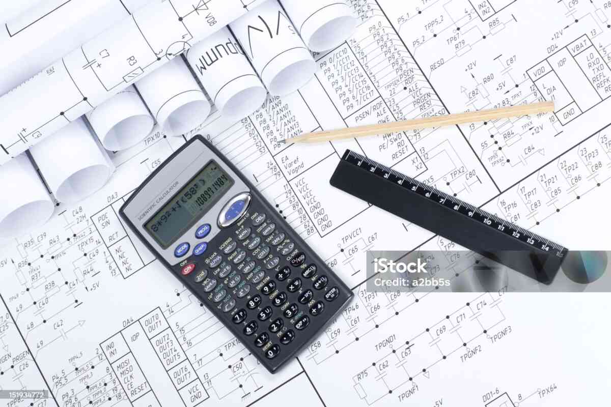
Capacitors are among the most widely used components in modern electrical and electronic systems. From a tiny ceramic capacitor inside a smartphone to large capacitor banks used in industrial power systems, capacitance plays an important role in controlling, filtering, storing, and transferring electrical energy.
A Capacitance Calculator makes it easier to work with these components. Instead of manually rearranging formulas every time, users can enter known electrical values and calculate the required capacitance or another related quantity.
This comprehensive guide explains capacitance from the basics through practical circuit calculations. It covers capacitor formulas, unit conversions, series and parallel combinations, stored energy, RC circuits, practical component selection, and common calculation mistakes.
Understanding Capacitance
Capacitance describes how much electric charge can be stored for a given voltage.
The fundamental equation is:
Q = CV
Rearranging the equation gives:
C = Q/V
and:
V = Q/C
These three versions are essential when using a capacitance calculator.
Capacitance is measured in farads.
A capacitor with capacitance C stores charge Q when voltage V is applied.
The relationship is linear for an ideal capacitor:
- Higher capacitance means more charge can be stored at the same voltage.
- Higher voltage means more charge can be stored by the same capacitor.
Why the Farad Is Usually Too Large
The farad is the standard SI unit, but most practical capacitors have much smaller capacitances.
For example:
- 1 F = 1,000,000 µF
- 1 µF = 1,000 nF
- 1 nF = 1,000 pF
Typical electronic components may have values such as:
- 10 pF
- 100 pF
- 1 nF
- 10 nF
- 100 nF
- 1 µF
- 10 µF
- 100 µF
- 1,000 µF
Larger capacitor technologies can reach far higher values.
Capacitance Calculator Formula
The primary formula is:
C = Q/V
Suppose the capacitor contains:
Q = 0.005 C
and the voltage is:
V = 25 V
Then:
C = 0.005 / 25
C = 0.0002 F
Converting to microfarads:
C = 200 µF
This is exactly the type of calculation that an online capacitance calculator can perform.
Calculating Charge From Capacitance
If capacitance and voltage are known:
Q = CV
Suppose:
C = 470 µF
V = 12 V
Convert:
470 µF = 470 × 10⁻⁶ F
Then:
Q = 470 × 10⁻⁶ × 12
Q = 0.00564 C
Therefore:
Q = 5.64 mC
Calculating Voltage From Charge
If charge and capacitance are known:
V = Q/C
Suppose:
Q = 2 mC
C = 100 µF
Convert:
2 mC = 0.002 C
100 µF = 0.0001 F
Then:
V = 0.002 / 0.0001
V = 20 V
Capacitor Energy Calculator
A capacitor stores energy in its electric field.
The energy equation is:
E = ½CV²
This formula is particularly important because voltage is squared.
For example, consider:
C = 1,000 µF
V = 100 V
Convert:
1,000 µF = 0.001 F
Then:
E = ½ × 0.001 × 100²
E = 5 J
Therefore, the capacitor stores approximately:
5 joules
The stored energy can become substantial in high-voltage or high-capacitance systems.
Why Voltage Matters So Much
Consider a fixed capacitor.
If voltage changes from 10 V to 20 V, voltage doubles.
But energy follows V².
Therefore:
- 10 V → proportional energy factor 100
- 20 V → proportional energy factor 400
The energy therefore becomes four times larger.
This is why large charged capacitors can present a significant electrical hazard even after a circuit has been switched off.
Equivalent Capacitance
When multiple capacitors are connected, their effective capacitance can be calculated.
There are two major configurations:
- Parallel
- Series
Understanding these configurations is essential when designing or modifying circuits.
Capacitors in Parallel
Parallel capacitors behave like a larger capacitor.
The equation is:
Ctotal = C1 + C2 + C3 + … + Cn
Example:
C1 = 4.7 µF
C2 = 10 µF
C3 = 22 µF
Ctotal = 4.7 + 10 + 22
Ctotal = 36.7 µF
This arrangement is useful when a designer needs greater total capacitance.
Capacitors in Series
Series capacitors produce a smaller equivalent capacitance.
For two capacitors:
Ctotal = C1C2/(C1+C2)
Suppose:
C1 = 10 µF
C2 = 10 µF
Then:
Ctotal = 100/20
Ctotal = 5 µF
Two identical capacitors in series therefore produce half the capacitance of either capacitor.
For three or more capacitors:
1/Ctotal = 1/C1 + 1/C2 + 1/C3 + …
Voltage Distribution in Series Capacitors
When capacitors are connected in series, the voltage distribution depends on their capacitances and other practical factors.
For ideal series capacitors, each capacitor carries the same magnitude of charge.
Because:
V = Q/C
a smaller capacitance can experience a larger voltage for the same charge.
Therefore, when using capacitors in series for voltage-related applications, the voltage rating of each individual capacitor must be considered carefully.
Capacitance and RC Time Constant
Capacitors often work together with resistors.
The RC time constant is:
τ = RC
where:
- R = resistance in ohms
- C = capacitance in farads
- τ = time constant in seconds
Suppose:
R = 100 kΩ
C = 10 µF
Then:
R = 100,000 Ω
C = 0.00001 F
Therefore:
τ = 100,000 × 0.00001
τ = 1 second
This gives engineers a convenient way to estimate charging and discharging behavior.
Capacitor Charging
For an ideal capacitor charging through a resistor from a DC voltage source:
Vc(t) = Vsource(1 − e⁻ᵗ/RC)
This equation shows that charging is exponential rather than instantaneous.
At approximately:
- 1τ → 63.2%
- 2τ → 86.5%
- 3τ → 95.0%
- 4τ → 98.2%
- 5τ → 99.3%
of the final voltage.
A capacitance calculator combined with an RC time-constant calculation can therefore help predict circuit timing.
Capacitor Discharging
During discharge:
Vc(t) = Vinitial e⁻ᵗ/RC
The voltage decreases exponentially.
After five time constants, the capacitor has discharged to a very small fraction of its initial voltage under ideal conditions.
This behavior is useful in:
- Timing circuits
- Delays
- Pulse shaping
- Filters
- Sensor circuits
- Control systems
Capacitance in Filters
Capacitors are essential components in many electrical filters.
A capacitor’s impedance depends on frequency:
Xc = 1/(2πfC)
Where:
- Xc = capacitive reactance in ohms
- f = frequency in hertz
- C = capacitance in farads
As frequency increases, capacitive reactance decreases.
This property allows capacitors to behave differently at different frequencies.
Capacitive Reactance
Suppose:
f = 1,000 Hz
C = 1 µF
Convert:
C = 0.000001 F
Then:
Xc = 1/(2π × 1,000 × 0.000001)
Xc ≈ 159.15 Ω
Therefore:
Capacitive reactance ≈ 159 Ω
At a higher frequency, the reactance would be lower.
Cutoff Frequency of an RC Filter
For a basic first-order RC filter, cutoff frequency can be calculated using:
fc = 1/(2πRC)
Suppose:
R = 10 kΩ
C = 100 nF
Then:
R = 10,000 Ω
C = 0.0000001 F
fc = 1/(2π × 10,000 × 0.0000001)
fc ≈ 159.15 Hz
Therefore:
Cutoff frequency ≈ 159 Hz
This equation is commonly used when designing basic filters.
Choosing a Capacitor Value
A capacitance calculation provides a theoretical value, but selecting a physical capacitor requires additional considerations.
Important specifications include:
Capacitance
The nominal capacitance must meet the circuit requirement.
Voltage rating
The capacitor must safely withstand the expected voltage.
Tolerance
Tolerance indicates how far the actual capacitance may differ from the nominal value.
Temperature characteristics
Some capacitors change capacitance significantly with temperature.
ESR
Equivalent series resistance can affect performance, particularly in high-current and high-frequency circuits.
Ripple current
In power applications, ripple-current capability can be critical.
Frequency
Some capacitor technologies perform better at particular frequencies.
Polarity
Certain capacitors are polarized and must be installed correctly.
Reading Capacitor Markings
Capacitors may be marked in several ways.
Some components show the capacitance directly, such as:
100 µF
Small ceramic capacitors may use numerical codes.
For example, a three-digit code can represent capacitance in picofarads under common marking conventions.
A marking such as 104 commonly represents:
10 × 10⁴ pF
which equals:
100,000 pF
or:
100 nF
However, capacitor marking systems can vary, so the manufacturer’s documentation should be consulted when identification is uncertain.
Capacitance Measurement
A capacitance calculator calculates values from known parameters. A capacitance meter measures the actual electrical component.
A digital multimeter may include a capacitance function, although measurement capabilities vary.
When measuring a capacitor:
- Disconnect power.
- Isolate the capacitor where appropriate.
- Ensure it is safely discharged.
- Select the correct measurement mode.
- Connect the test leads correctly.
- Allow the instrument to settle.
For safety-sensitive circuits, follow appropriate electrical procedures and manufacturer instructions.
Calculated Capacitance vs Measured Capacitance
A calculated value represents a theoretical or design requirement.
A measured value represents the actual component under particular test conditions.
These values may differ because of:
- Component tolerance
- Temperature
- Frequency
- Aging
- Measurement method
- Parasitic effects
Therefore, a calculator and a capacitance meter serve different purposes.
Practical Example: Designing a Smoothing Capacitor
Suppose an engineer needs to estimate capacitance for a DC power supply.
The required capacitance depends on factors including:
- Load current
- Ripple frequency
- Allowed ripple voltage
A simplified approximation for capacitor ripple is:
C ≈ I/(fΔV)
Where:
- C = capacitance
- I = load current
- f = ripple frequency
- ΔV = allowed voltage ripple
For example, assume:
I = 1 A
f = 100 Hz
ΔV = 2 V
Then:
C ≈ 1/(100 × 2)
C ≈ 0.005 F
Therefore:
C ≈ 5,000 µF
This is a simplified design estimate. Real power-supply design must account for capacitor ESR, diode behavior, transformer characteristics, load variation, temperature, component tolerance, transient conditions, and safety requirements.
Practical Example: Parallel Capacitors
Suppose a circuit requires approximately 150 µF, but the available capacitors are:
- 100 µF
- 47 µF
- 2.2 µF
Connecting them in parallel gives:
100 + 47 + 2.2
149.2 µF
This may be close to the target, depending on the circuit’s tolerance requirements.
Practical Example: Series Capacitors
Suppose two 100 µF capacitors are connected in series.
Ctotal = (100 × 100)/(100 + 100)
Ctotal = 10,000/200
Ctotal = 50 µF
This demonstrates why simply adding series capacitor values would produce an incorrect answer.
Capacitance Calculator for Students
Students studying electronics and electrical engineering can use a capacitance calculator to verify homework and laboratory calculations.
It can help reinforce:
- SI units
- Scientific notation
- Algebraic rearrangement
- Series and parallel circuits
- Energy calculations
- RC time constants
- Capacitive reactance
- Filter calculations
The calculator should support learning rather than replace understanding. Students should know which formula applies and why.
Capacitance Calculator for Engineers
Engineers can use calculators during preliminary design and verification.
Common uses include:
- Component selection
- Filter design
- Timing calculations
- Energy estimation
- Power-supply design
- Sensor circuits
- Signal conditioning
- Frequency response calculations
For final designs, calculations should be verified against engineering standards, component datasheets, simulations, testing, and applicable safety requirements.
Capacitance Calculator for Electronics Hobbyists
Hobbyists frequently encounter capacitor values while repairing or building circuits.
A calculator can help determine:
- Equivalent capacitance
- Stored energy
- RC time constants
- Capacitive reactance
- Filter cutoff frequency
It can also help when combining commonly available capacitor values to approach a desired value.
Capacitors in Automotive Electronics
Modern vehicles contain numerous capacitors.
Applications include:
- Engine control modules
- Audio systems
- Sensor circuits
- Communication networks
- Power electronics
- Ignition systems
- Motor controllers
- Electric vehicle systems
Automotive environments can expose components to vibration, temperature changes, electrical transients, and other demanding conditions. Therefore, calculations alone are insufficient for selecting automotive-grade components.
Capacitors in Power Electronics
Power electronics can require capacitors capable of handling:
- High voltage
- High ripple current
- Rapid switching
- Temperature changes
- High-frequency currents
Applications include:
- Inverters
- Motor drives
- DC-link circuits
- Power converters
- Renewable-energy systems
- Battery systems
For these applications, capacitor technology and electrical ratings are especially important.
Common Capacitance Calculator Errors
Entering the wrong unit
Entering 10 µF as 10 nF creates a result that is off by a factor of 1,000.
Forgetting scientific notation
Small capacitor values often require powers of ten.
Confusing series and parallel
The equations are fundamentally different.
Ignoring capacitor tolerance
A calculated 100 µF target does not necessarily mean a physical capacitor will measure exactly 100 µF.
Ignoring voltage
A capacitor with the correct capacitance may still be unsafe if its voltage rating is inadequate.
Ignoring frequency
Capacitor behavior depends on frequency, especially in AC and high-frequency applications.
Frequently Asked Questions
What does capacitance mean?
Capacitance is a measure of a component’s ability to store electric charge relative to voltage.
What formula is used to calculate capacitance?
The basic formula is:
C = Q/V
What is 1 µF in farads?
1 µF = 0.000001 F
What is 1 nF in microfarads?
1 nF = 0.001 µF
What is 1 pF in nanofarads?
1 pF = 0.001 nF
Do capacitors store energy?
Yes. The ideal stored-energy relationship is:
E = ½CV²
Do capacitors in parallel increase capacitance?
Yes. Their capacitances add.
Do capacitors in series increase capacitance?
No. The equivalent capacitance is smaller than the smallest individual capacitance for ordinary positive capacitors.
Can a calculator replace capacitor testing?
No. A calculator provides a theoretical result. A suitable meter or test instrument is required to measure an actual component.
Conclusion
A Free Capacitance Calculator is a practical tool for solving capacitor-related equations quickly and accurately. It can be useful for basic calculations involving charge and voltage as well as more advanced calculations involving stored energy, equivalent capacitance, RC time constants, reactance, and filter frequency.
The most important equations to remember are:
C = Q/V
Q = CV
V = Q/C
E = ½CV²
τ = RC
Xc = 1/(2πfC)
fc = 1/(2πRC)
Knowing these relationships makes it much easier to understand capacitor behavior and use an online calculator effectively.
For real-world applications, always go beyond the calculated capacitance and verify voltage rating, tolerance, temperature rating, ESR, ripple current, polarity, frequency characteristics, physical dimensions, and manufacturer specifications.


